| 1932 Ford Hot Rod |


| 1 2 3 4 5 |
| 6 7 8 9 10 |
| 11 12 13 14 15 |
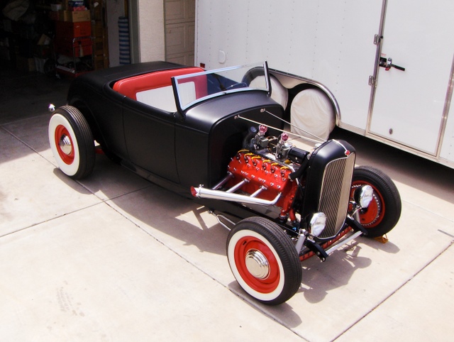
One of my current projects is a 1932 Ford Hot Rod. I have always wanted to build one of these. They are such cool cars. In photos 1 & 2 you
can see a view of the floor board. Photo 3 shows the rear section. Photo 4 shows the hair pin. I purchased the seat frame from Glide. It came
powder coated and you can see it in photo 5. Photos 6-9 shows the dash board with the gauges. In photo 10 you can see the dash installed in
the car with the gauges. The new 1940 Ford steering wheel can be seen in photo 11, and photo 12 gives you a view of the steering column that
Doug Reynolds made for me. Photo 13 is of the pedal assembly which will be modified later changing the landing angle. Photo 14 shows the
steering U joints and in photo 15 you can see the rack and pinion steering assembly.
| 16 17 18 19 20 |
| 21 22 23 24 25 |
| 26 27 28 29 30 |
Photo 16 is of the brake line routing. In photo 17 you can see the front end installed. A dummy motor for reference is in photo 18. In photo 19
you can see the forming of the front brake lines around the cross member. Photo 20 gives a view of the front shock. You can see the rear end
assembly in photo 21. Photo 22 shows the rear end after it was powder coated. I am putting in a 1939 Zephyr transmission and this can be seen
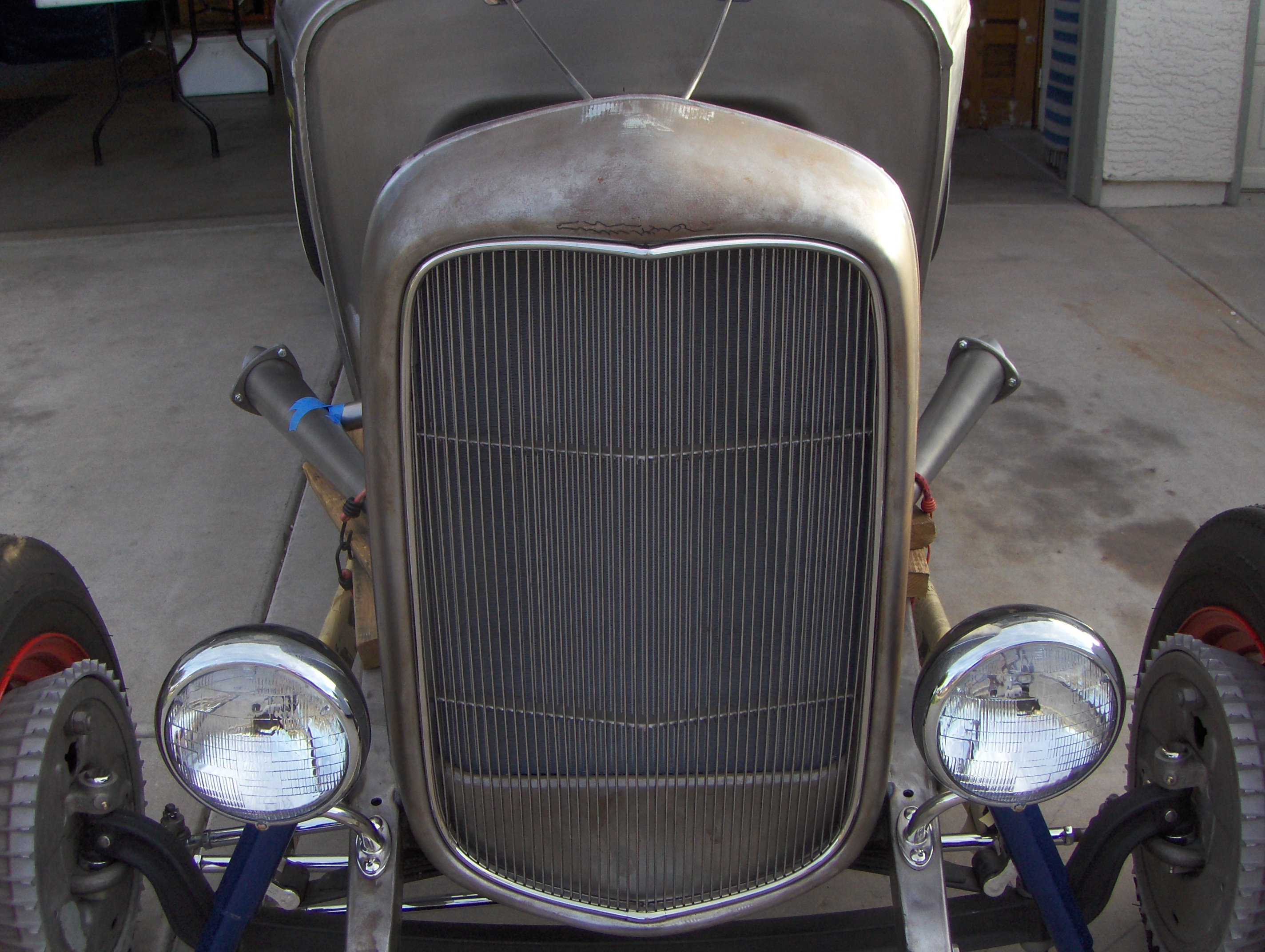
in photo 23 & 24. Photo 25 shows the transmission mount. Photo 26 shows the rolling chassis. Photo 27 gives a view of the front grill installed
and of the headlights. Photo 28 shows a side view. The fuel tank was installed as can be seen in photo 29. I needed help to lift the body onto a
homemade dolly. Three of my friends came to my rescue and you can see us discussing the best way to do it in photo 30.
you can see the forming of the front brake lines around the cross member. Photo 20 gives a view of the front shock. You can see the rear end
assembly in photo 21. Photo 22 shows the rear end after it was powder coated. I am putting in a 1939 Zephyr transmission and this can be seen
in photo 23 & 24. Photo 25 shows the transmission mount. Photo 26 shows the rolling chassis. Photo 27 gives a view of the front grill installed
and of the headlights. Photo 28 shows a side view. The fuel tank was installed as can be seen in photo 29. I needed help to lift the body onto a
homemade dolly. Three of my friends came to my rescue and you can see us discussing the best way to do it in photo 30.
| 31 32 33 34 35 |

| 36 37 38 39 40 |

| 41 42 43 44 45 |
Photos 31-33 shows us lifting the body unto the dolly. Not bad for a bunch of old guys, although we sure enjoyed our break (photos 34-36).
Photos 37- 40 shows the modification that Matt Howard from Deluxe did to the firewall. In photos 41- 44 you can see the underside of the
body where Matt had modified it for the drive shaft torque tube to clear. Here I am in photo 45 torquing the heads on the V12 Lincoln engine.
Photos 37- 40 shows the modification that Matt Howard from Deluxe did to the firewall. In photos 41- 44 you can see the underside of the
body where Matt had modified it for the drive shaft torque tube to clear. Here I am in photo 45 torquing the heads on the V12 Lincoln engine.


| 46 47 48 49 50 |


56 57 58 59
I am using a pair of Stromberg carburetors on an Edmunds intake manifold and these can be seen in photos 46 & 47. I made copper oil lines
for the oil filter system (photos 48 & 49). In photo 50 you can see the starter that was powder coated and the chrome band around it. You can
see the distributor and the coil was modified to 12 volts in photo 51. I had the generator rebuilt to 12 volts and powder coated and this can be
seen in photo 52. Photo 53 shows the engine block water drain plug. I put the engine on a cart (photo 54-58) that my good friend Dave
Edmonds built in order to move it around. Those things are heavy! The engine is almost done (photo 59) and now I will start to build the
exhaust system. Now that the Toyopet is done I hope to complete the 32 soon.. It sure looks negleted sitting in the garage,but not for long.
| Home About Us Bug-In Photos Contact Us Frenchy Interview Index Links Magazine Articles Race Cars The Museum The Original Shrine The Shrine #2 |
| (Click on the photos to see a larger view.) |


60 61 62 63 64
70 71 72 73 74
65 66 67 68 69
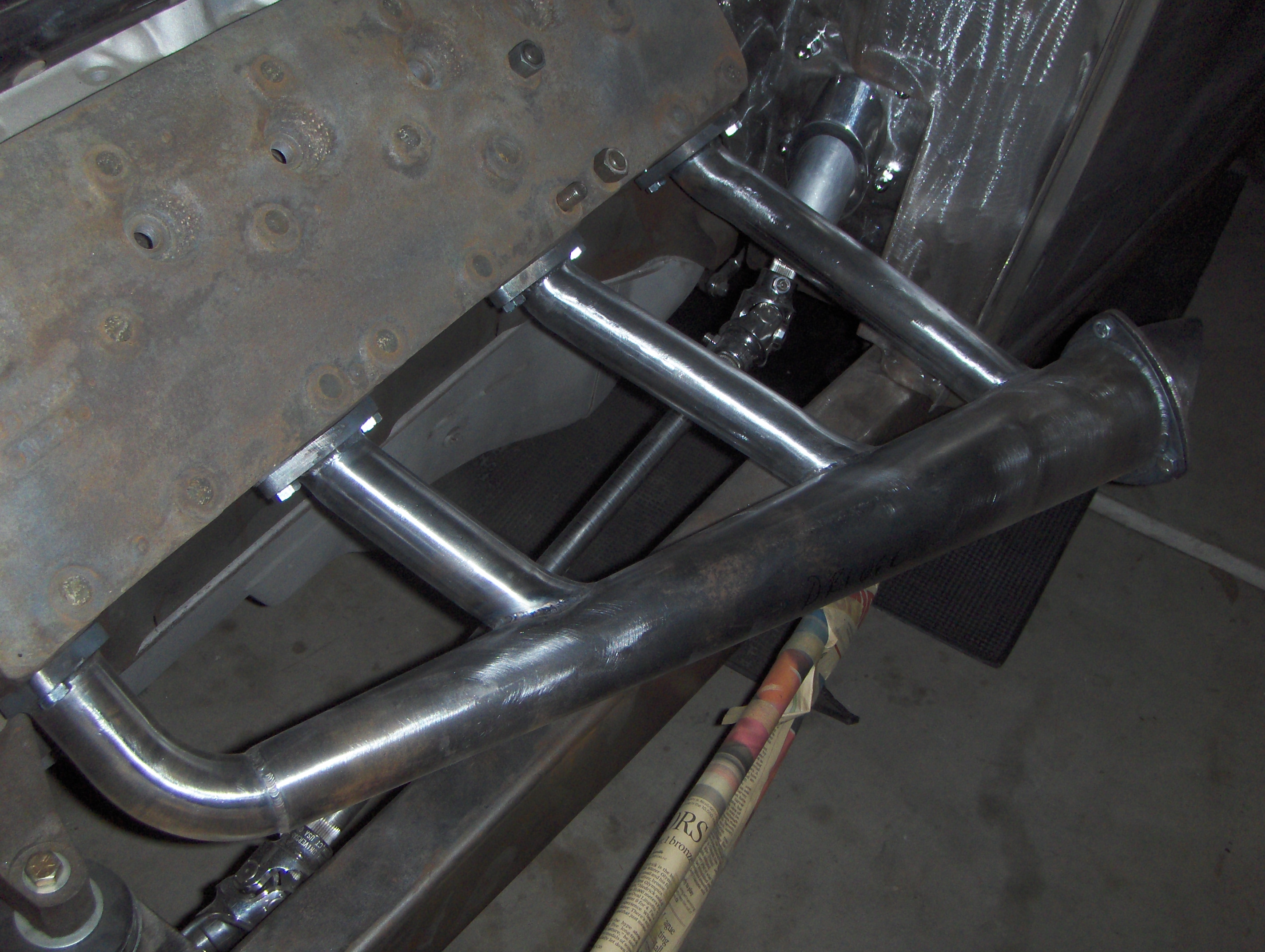
Photo 60 depicts the alignment of the exhaust. You know me, it just had to be perfect! In photos 61 and 62 I had modified the firewall for the
steering column and the oil filter lines. Pedals assembly photo 63. Granddaughter Jacqueline loves to "help" me in the garage. I'm sure she is
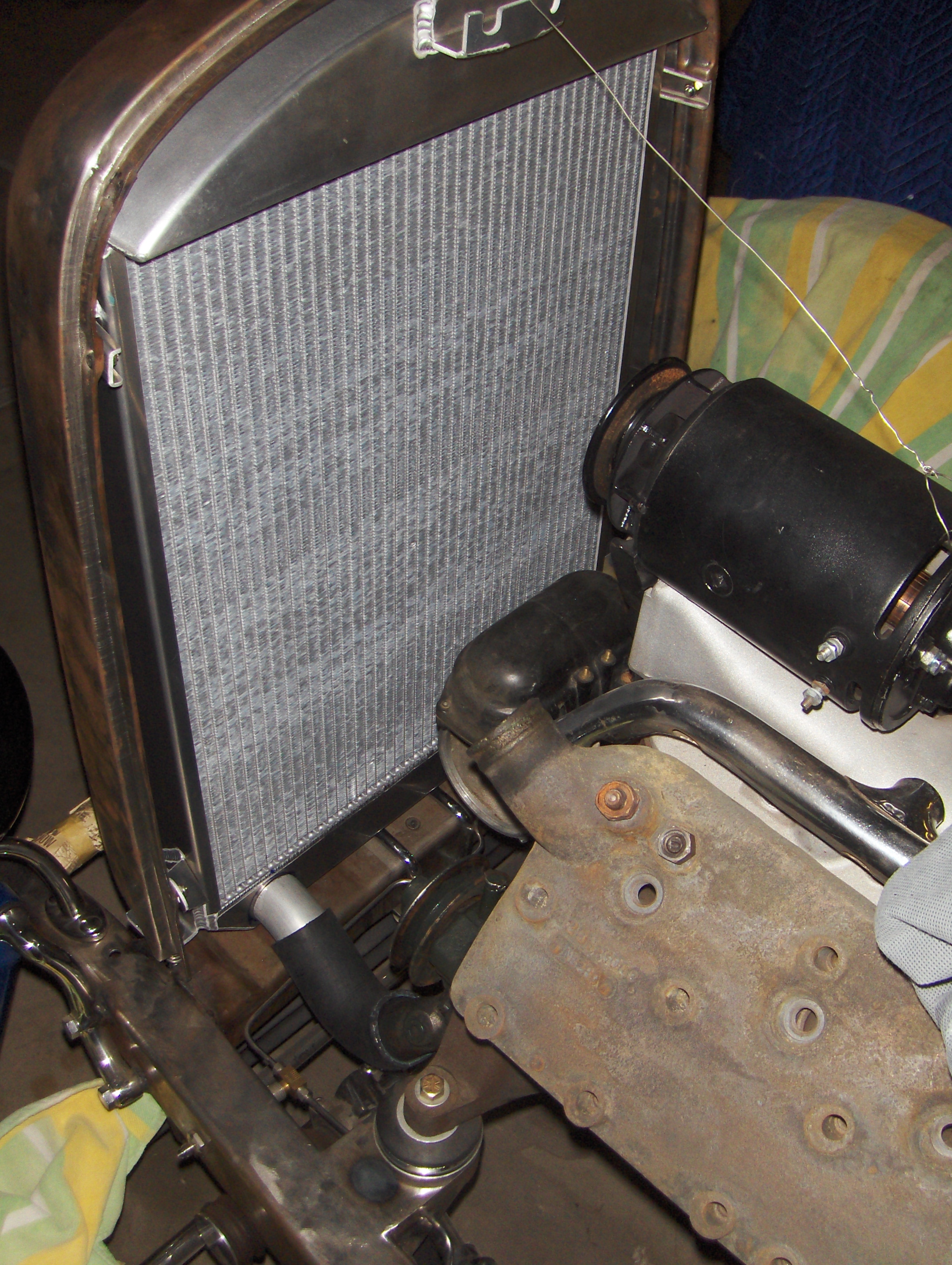
dreaming of the day when we will take a ride in the '32 (photos 64 to 66). Photo 67 shows a Ron Davis custom made radiator. I was trying to fit
the upper radiator neck. Looking at photo 68 you can see that after a few adjustments this is the angle where they will be welded into place.
Photo 69 depicts what it looked like after Ron had welded the upper and lower tubes as well as the radiator rods support. Here is a difficult
angle (photo 70) where it meets the water pumps. Photos 71 and 72 gives a view of fitting in the one piece rubber floor mat. In photos 73 and
74 you can see my friend Eric welding the exhaust pipe flanges.
steering column and the oil filter lines. Pedals assembly photo 63. Granddaughter Jacqueline loves to "help" me in the garage. I'm sure she is
dreaming of the day when we will take a ride in the '32 (photos 64 to 66). Photo 67 shows a Ron Davis custom made radiator. I was trying to fit
the upper radiator neck. Looking at photo 68 you can see that after a few adjustments this is the angle where they will be welded into place.
Photo 69 depicts what it looked like after Ron had welded the upper and lower tubes as well as the radiator rods support. Here is a difficult
angle (photo 70) where it meets the water pumps. Photos 71 and 72 gives a view of fitting in the one piece rubber floor mat. In photos 73 and
74 you can see my friend Eric welding the exhaust pipe flanges.
75 76 77 78 79
80 81 82 83 84
85 86 87 88 89
The exhaust on the right side is done as can be seen in photo 75. Here is a top view of it (photo 76). I was making sure it was centered. Photo
77 shows a view from the left side. The body is removed from the frame (photo 78) and will be going to be powder coated. The fuel
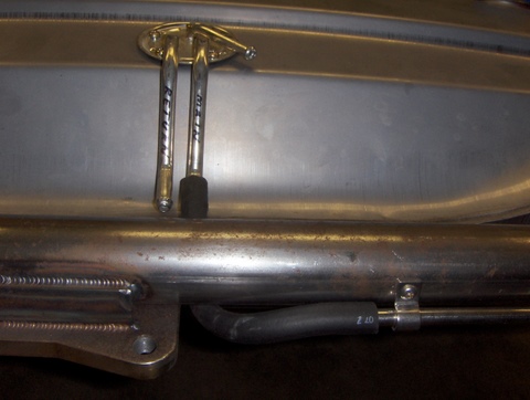
pump/filter and the regulator are mounted (photo 79). Here in photo 80 I am routing the soft fuel line to a hard line with clamps. The other line
next to it is a return line if you have a fuel injection system. In picture 81 you can see the hard line mounted on the chassis. In photo 82 the
hard line is leaving the fuel pressure regulator to meet the manual fuel pump on the engine . In photo 83 all the parts are on the table to be
inspected and cleaned. In photo 84 the front backing plates are from a 1947 Lincoln rear . Here in photo 85 is the transmission from a 1939
Lincoln Zephyr. I took the transmission apart to be certain it was good. Photo 86 shows a view of the chassis about to go to the powder coater
and done in gloss black. Here it is back home (photo 87). I installed the banjo rear end. Next was the front end reassembly, along with some
detailing (photo 88). On the fourth day the car was rolling out of the garage (photo 89) and the front end will be aligned soon.
77 shows a view from the left side. The body is removed from the frame (photo 78) and will be going to be powder coated. The fuel
pump/filter and the regulator are mounted (photo 79). Here in photo 80 I am routing the soft fuel line to a hard line with clamps. The other line
next to it is a return line if you have a fuel injection system. In picture 81 you can see the hard line mounted on the chassis. In photo 82 the
hard line is leaving the fuel pressure regulator to meet the manual fuel pump on the engine . In photo 83 all the parts are on the table to be
inspected and cleaned. In photo 84 the front backing plates are from a 1947 Lincoln rear . Here in photo 85 is the transmission from a 1939
Lincoln Zephyr. I took the transmission apart to be certain it was good. Photo 86 shows a view of the chassis about to go to the powder coater
and done in gloss black. Here it is back home (photo 87). I installed the banjo rear end. Next was the front end reassembly, along with some
detailing (photo 88). On the fourth day the car was rolling out of the garage (photo 89) and the front end will be aligned soon.
90 91 92 93 94
95 96 97 98 99
Photo 90 gives a view of the front seat. It was upholstered by a friend in California, Lenny Copp (West Coast Classics). Photo 91 displays the
stainless brake lines. You can see that the front and rear brakes share their own reservoir in photo 92 & 93. Looking at photo 93 you can see
the brake light switch wiring running into a stainless tube. This was done for additional detail. Hey, they don't call me Dr. Detail for nothing! It
was the same for the rear fuel tank sending unit wire (photo 94), which also ran into a stainless tube. Look at the chassis just waiting for the
engine to be installed in photos 95 and 96! Photo 97 gives a close-up view of the Coker Firestone white wall 500/525 x 16 tire. You are
looking at the rear in photo 98. Next will be the installation of the fuel tank. Another Coker 750 x 16 wide white wall tire as seen in photo 99.
In photos 100-102 Tim Benedict, a friend and fellow hot rodder, stopped by to do my front end alignment. I am ready to install the engine on
the chassis in 103 and 104.


100 101 102 103 104
105 106 107 108 109
110 111 112 113 114
115 116 117 118 119
The engine is installed (photos 105-108) with the transmission. Now I am waiting for the body and radiator to continue on. I went over the
entire body in photo 109 and took care of any imperfections before taking it to be powder coated. Photo 110 shows the body ready to go to
Full-Race Motorsports to have brackets for mounting the seat belts installed on the underside. Before it was loaded on to the trailer my son
Marc did some welding (photos 111-113) with daughter Jacqueline lending a helping hand. In photo 114 you can see the tube being installed
for the rear deck lid cable. Looking at photo 115 you can see the throttle that was installed . Photos 116 and 117 shows the inspection plate for
the master and clutch cylinder reservoir. My friend Matt Todd fabricated a foot rest for the gas pedal (photo 118). I used a 1936 Lincoln
Zephyr rear deck lid handle for my shift knob, which can be seen in photo 119..
120 121 122 123 124
125 126 127 128
In photos 120-122 shows how Mark, the owner of Sun Western Coating, power washed the body with chemicals to remove the oil residue
before it was powder coated. We had to manually brush on pool acid to make sure the body was clean. Photos 123 and 124 shows the body
being powder coated before going into the oven. Here it is out of the oven (photos 125-128). You can see the result after it was in the oven for
1 hour at 400 degrees . The windshield and driver's seat are installed (photo 129). In photos 130 and 131 you can see where I installed the
gauges and steering wheel.
132 133 134 135 136
137 138 139 140
141 142 143 144 145
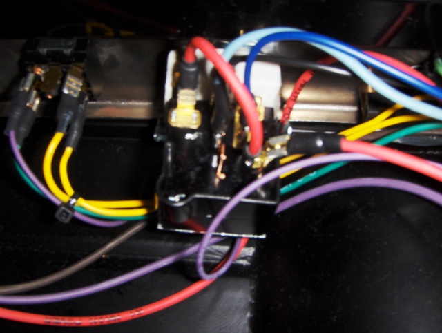
Photos 132-136 shows the wiring that was installed under the seat. A good friend of mine, Asher Emerson, did the pin stripping.. It turned out
beautiful. I especially like what he put on the rear deck lid (photo 137). It was Asher's idea to write Hot Rod Lincoln on the fuel tank (photo
138). The V12 emblem on the nose of the radiator shell (139 & 140) was Asher's wife's idea. That was sure a great idea!
It was nearing completion and in photos 141-143 I rolled it out to admire it. Soon after the floor panel came back from the powder coater
(photo 144) and I can finally say it is finished. Now I can take it for a drive. My wife Judy took this picture as I was driving down the street on
August 31, 2009, which was 6 years to the day that I had started this project. It was my goal to complete it on this day and I succeeded.
129 130 131


51
52
53
55
54